
Yeh, that’s right. Electronic shifter: a touring bike with something battery powered : o
The Need
TLDR: thousands of shifts and 3 months of standby battery life for my non-destructive electronic shifter. If you love your vintage rig but want to add some precision (or just a bit of fun), keep on reading.
Prototyping for the bar end shifters required a lot of patience. It wasn’t just about getting the look and feel of the shifters right (which, arguably I still haven’t done) it was really about the user experience. I wanted my shifts to be fast, repeatable, and precise.
Fast was probably the easiest to design for. There were a few iterations that tolerances were a little tight, and they could be pretty tough to move. I sheared a few of the first ones clean off. But as long as the detent wasn’t too detent-y, the speed of the shift was only a matter of how quickly I could get to the bar ends.
Unless, of course, the precision of the gear-distance was off.
If the shifters weren’t tuned to the cassette properly (and gear-to-gear distances differ by tenths of a mm) the shift would be jumpy, noisy, and it was possible that it wouldn’t even complete. Annnnnd… well, this happened A LOT during prototyping.
The noise, noise, noise!

Here’s, like, the full complaint: My touring bike is fully loaded with racks, panniers, water bottles, bladders, tools, pump, a lock, handlebar bag, saddle bag, frame bag….all with zippers, clasps, hardware, and the like. And I have systematically eliminated every single stray noise on that machine. If you have spent 80 miles a day for 60 straights days in a saddle, you have a lot of time to get annoyed. And few things in this world annoy me more than repetitive noises. Perhaps with the exception of repetitive AND preventable, noises.
All of this color commentary to say that I really hate noisy shifting. I am a mechanical engineer (well, half of one anyway), and I should be able to tune my derailleur to perfection.
Help Wanted: Precision
So that was part of the design process for the bar end shifters. There was a lot trial and error and in situ testing at first, and every time I needed to make a change to the gear-distances it meant 6 more hours of printing because, you know, the distances are “hard-coded” into the plastic.
Well, that got old very quickly (Or very slowly, I guess, while I waited for the prints to finish so I could ride my bike).
What I needed was a bench top actuator to measure cable pull per gear change so I could accurately model the distances in cad and print them out on the shifters. What I needed was precision. Precision, almost by definition, takes time. And if I was going to take the time to build it, well, I should just go the extra mile and turn that benchtop-actuator into a bike-mounted-actuator… because automation right?
So about halfway through the development of the bar end shifters I started to think about, and then work on, the upgraded solution, the holy grail: an electronic shifter. I mentioned this back in my first post, and you can head back there for a bit of background, but I’ll do my best to quickly sum up the lay of the land here.
Existing Solutions
- Off the shelf
- X-shifter took everyone’s money and then moved to Bali or something.
- Archer Components has a solid electronic shifter.
- Homebrew
- This guy carriers around a lead acid battery with him!
- And you could always go the route of modifying your derailleur to remove and then simulate the behavior of the return spring.
There are components of each of those designs that show merit. Archer’s product is beautiful and it work, but their weakness stems from the actuator. They use a servo motor and servo motors require constant power to maintain position…and that’s not a great requirement for a battery powered device.
The best of all worlds
I didn’t want any of those. I don’t like Bali, Archer’s battery only lasts a few days, I care about the weight of my load, and I didn’t want to permanently alter my stuff.
Removing the derailleur spring, on the other hand, allows for the use of a stepper motor. Steppers have high holding torques and, in comparison to servos, only require power when moving (the stepper detents and magnets provide the opposing force).
Intermittent power requirements? Great for batteries. But alas, you’d have to mutilate your stuff. Your precious, beautiful stuff.
So why didn’t I want to alter my derailleur? Because I love it, that’s why. Actually, I love all of my derailleurs. Even this broken one. And if someone else on the internets (sic) wants to use this design, well maybe they don’t want to break their stuff either. I’m trying to be democratic.
Electronic Shifter: Ideate
Design Requirements
So I had some starting points for the design of my electronic derailleur shifter:
- No modification to existing gear;
- Long battery life (1 month +)
- Low weight (let’s say less than a pound, including battery);
ok how to get there? Let’s look at a derailleur and see if we can simplify the mechanics a bit.
Some, uh, engineering
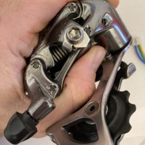
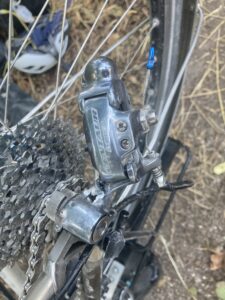
Actually we don’t need to simplify them, it’s basically a practice problem in an undergraduate mechanics text. Derailleurs are parallelograms with an extension spring (that we’ll call the derailleur-spring) connecting two nodes.
Your cable, and therefore your shifter, pulls the other two nodes together, causing the derailleur spring to elongate. The force of the spring (-kx for the wonks) is balanced by the reaction force in your shifter. It’s in static equilibrium when not being shifted.
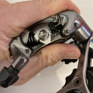
So inserting an actuator into this design means that you’re constantly fighting against that derailleur spring (unless you remove it). The problem is that an actuator (at least the ones we’re looking at) can do work in both directions. The spring is redundant in the best case (it helps on the return) and inefficient in the worst. I mean, I get why removing it makes sense.
Perpetual Motion
But, you know, it’s kinda nice of that spring doing all of that return work for your system. Wouldn’t it be cool if we could somehow use that spring to our advantage. Wouldn’t it be, like, super cool if that spring could be used to help us in both directions!
I’m glad I got your attention. But…seriously, this idea of spring balancing reminds me of something…
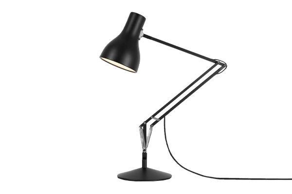
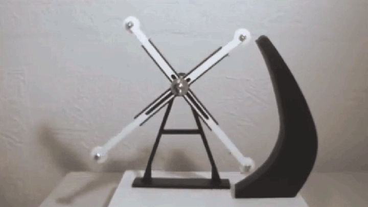
These lights are SOOOOO cool, I remember being fascinated by them as a kid. You had this massive light that could be moved with the lightest of touches. And look at all of those springs, how the hell does that work?
It turns out the mechanism is called a Energy Free Spring-to-Spring Balancer. And this guy, who studied the shit out of them, is my official mechanical engineering hero:
Energy Free Spring Balancers
I actually read his thesis and it was awesome. Now, I’ve browsed thesises (thesi?) before but never had the desire to finish one…this was different. It was exciting. It was well written. It motivated me to blow the dust off of my mechanics book to keep up with the math.
And, per our electronic derailleur shifter, it was relevant. Check out this diagram from one of his papers in the Journal of Mechanical Design
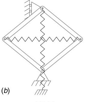
Look familiar? It’s basically our derailleur with an an equal extension spring (we’ll call this one the balancer-spring) across the bare nodes of the parallelogram. You can do the math (you have to understand what a zero-length spring is first) but no matter the position of the nodes, the parallelogram will be in static equilibrium!
Actually, I love math, and it’s pretty basic so I added a quote from Herders Thesis below:
When the two equal spring[s] are shifted towards each…the balanced parallelogram results… [This] demonstrates that any parallelogram, with equal ideal springs on its diagonals, yields a statically balanced spring mechanism
\( U(l_1,l_2) = \frac{1}{2} k_1 l_1^2 + \frac{1}{2} k_2 l_2^2 \\ \)
\( U(l_1,l_2) = \frac{1}{2} k (l_1^2+l_2^2)\\ \)
\( l_1^2+l_2^2 = 2*(r_1^2+r_2^2) \\ \)
Where l are the diagonals (or spring lengths) and r are the sides of the parallelogram. Since r is a constant, substituting the 3rd equation into the 2nd yields \( U = Constant \)
Back to Physics
Well well well. Perpetual motion methinks not. Turns out we can use that derailleur-spring after all. In fact the only force needed to move that parallelogram (the ideal one above) is the force needed to overcome the internal friction of the system. The system, once displaced, will preserve it’s position without the need of an external force. Bye bye servo (sorry Archer!) and hello long battery life. Hello electronic shifter…
EXCEPT,
This is the real world. And, ummmm, unless you want to mount your electronic shifter to the derailleur (I don’t), we’re still going to need to use a cable to transmit that force. Cables are fine for pulling, great even! but, as my undergraduate physics professor liked to remind us (usually as a means to embarrass us), you can’t push a rope.
Not a Rope
Some good news though. Technically, the cable *isn’t* a rope. (News flash, I know). Cables, unlike rope, do have some usable stiffness. But also, more importantly, this rope cable is also sheathed in a cable housing so you can… kind-of… push this rope.
Other important note: if I were able to push on the cable, the input force would only need to match the internal friction of the system, and I could design for the actuator to be quite small. But I can’t and I need those springs to be slightly mismatched and that means I need the actuator to be…well, decent.
The good news for me is that I had an actuator laying around that is pretty impressive, and I wanted to use it in a project anyway. Soo I haven’t actually tested this with smaller actuators but I’m fairly confident that other’s would work just fine. I tried with my fingers and it’s super easy to move (try it without the balancer-spring and you’ll have to work for it). Hopefully someone else will provide some data.
This actually has two important results:
- My actuator doesn’t need to be super OP, and therefore
- I can use a smaller battery that saves weight AND lasts a long time
Actuators for Electronic Shifters
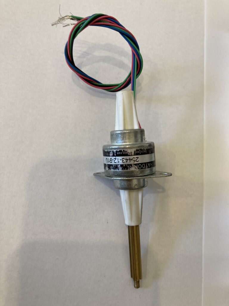
Right, so, actuators. Servo are out, steppers are in. But I need to turn the rotary motion of a motor into a linear motion of the cable…thankfully I’ve worked with electromechanical projects before and happen to have some favorite manufacturers. One of my favorites for linear actuators is Haydon Kerk (no affiliate links, ever). Highly recommended for their quality and documentation, I have about 30 of their products laying around the garage at any given time. Here’s what I had that worked:
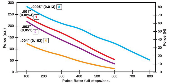
Haydon Kerk linear actuator 25443-05-912
- .013mm linear travel per step, 30mm total stroke
- 5V windings driven at 12V for < 25% Duty Cycle
- I’m able to actuate the derailleur at pulse rates as high as 900 s/sec
In truth, this thing would have worked without the balancing spring, it’s pretty strong.
These actuators are pretty much constant current, regardless of the load (assuming it’s within operating limits). This is typically one of the downsides of a stepper motor. But I want my shifts completing in 500 ms or so. So if I draw 1-Amp at 12V for 500 ms that’s not very many Joules (6, to be precise) and my tiny battery has lots of Joules (3700 mA-H (@3.7V) ~ 50,000 J).
Incidentally, this gives me about 8,000 shifts, but my tests gave over 10k. I’m guessing the difference was in the variable voltage of a Li-ion battery.
Electronic Shifter: Design
Where to put the balancer-spring? I didn’t want (and probably couldn’t) install the spring directly on the derailleur, so the next best place was on the actuator. Matching the spring was done empirically (using a fish scale to measure force vs displacement) and via physical inspection (measure derailleur-spring: width, compressed length, and wire diameter → find matching balancer-springs). For some reason I started the design with matching extension springs…probably because the derailleur spring is an extension spring and I was just excited to get started
Out with the old, in with the new
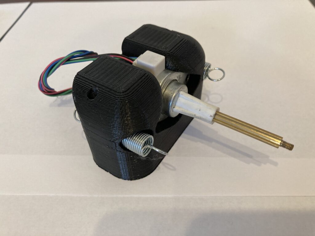
A matched balancer-spring installed on the actuator was a design challenge. The best I could come up with was two balancer-springs, each with half of the spring-constant of the derailleur-spring.
But then I realized that a matched compression spring would make for a sleeker design. A compression spring, unlike the extension spring, could be placed inline with the actuator and derailleur cable.
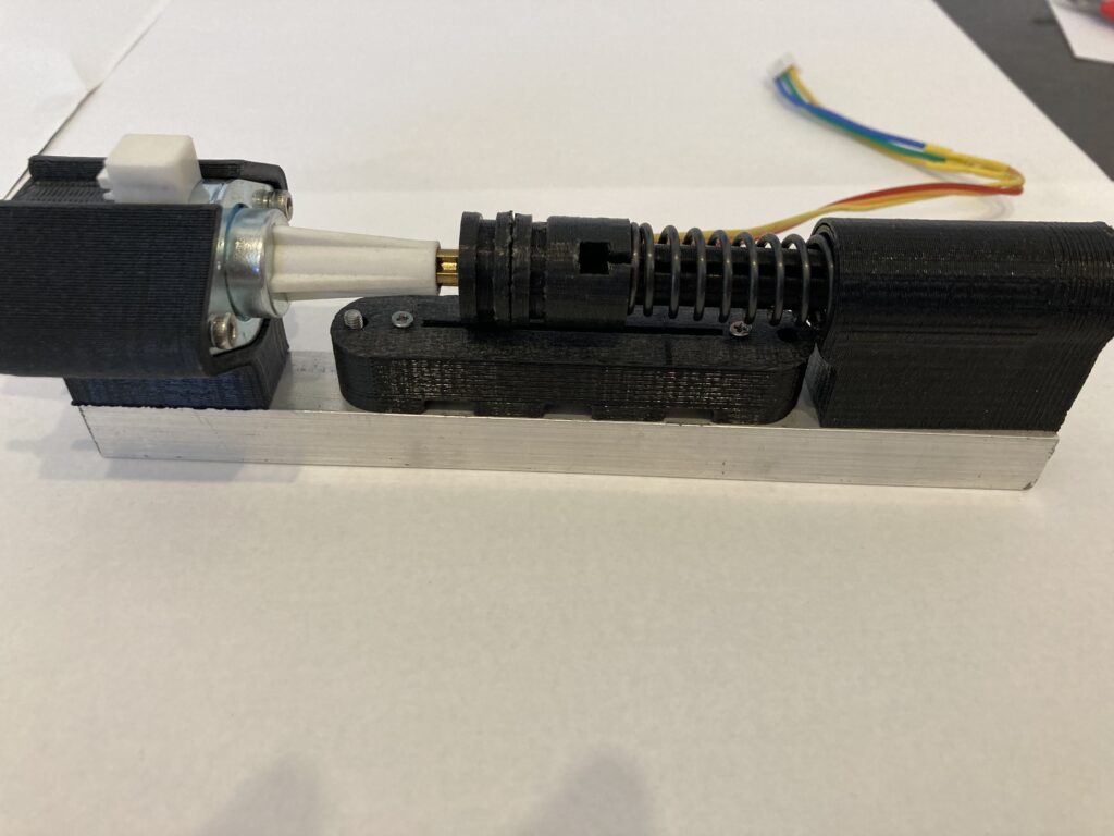
That first design was ugly. Though it definitely worked (and, just for giggles, it worked with coin cell batteries). Design is iterative after all. A compression spring, unlike the extension spring, could be placed inline with the actuator and the derailleur cable. If I had access to the back side of the actuator shaft, I could have installed an extension spring there. I didn’t…but some linear actuators do have that feature.
This required some assembly features that I don’t think are particularly slick but they get the job done. More on that in the mech design section. Maybe mark-3 will improve on these.
Time to test
Bench-top testing was fun. I blew a microcontroller while testing battery life, something to do with Adafruit’s dual power rig, when the battery failed it shorted my low bat pin to power and fried everything. But other than that it was pretty straightforward. Nail a derailleur to a piece of wood, connect actuator, verify it shifts gears through the entire range, attach battery, verify battery life. Boom, electronic shifter.
I did mess around with a variety of sleep modes and actuator profiles to optimize battery life. Full sleep on an arduino (which includes brown out detection) is not worth the risk for a battery powered device. I toasted one pro micro and had to rebuild the whole perf-board. Very frustrating. But I did desolder the on board regulator and led to cut down on the quiescent draw. I can’t remember, but I think the device draws 1-2 mA during sleep: That’s 2.5 months of standby battery life. Actual results were higher (again, due to non-conformities in Li-ion batteries)
Drum Roll Please
10,000+ shifts (stopped here, that was enough resolution to confirm my math) and 3 months of standby battery life from a 3700mah lithium ion battery. The latter was actually measured for 3 months.
Yep you read that right. 3 months of battery life from a battery the size of a credit card. Eat your heart out Archer!
Note here: first, don’t eat your heart out. Those guys are super cool. Second, standby test and shifting tests were separate. Actual battery life on the bike is closer to 1.5 months IF I forget to turn it off. More on that last bit in the final thoughts.
Real world values have actually tended higher and it’s been colder here lately. I’m up to twp months on the current charge and I’ve been riding almost daily.
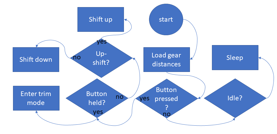
Code
The code for the testing was very very simple. Production required some more nuance.
- I needed some debouncing and figured I could do this in software (in hindsight, I would like to add a hardware debounce).
- I needed a calibration routine for the actuator / potentiometer couple;
- Need to save and recall gear distances in EEPROM;
- Need to be able to adjust gear distances on the fly (initial setup AND long term corrections, due to derailleur damage, cable stretch, etc)
The code is FOSS and is available on my github. It’s mostly commented and there are some extraneous functions that need to be removed but I think it’s fairly straightforward.
Algorithm is as follows:
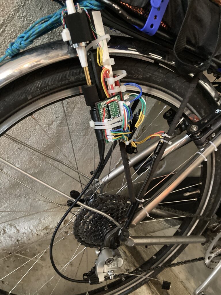
Electronics
Electronics are also straightforward. Components include:
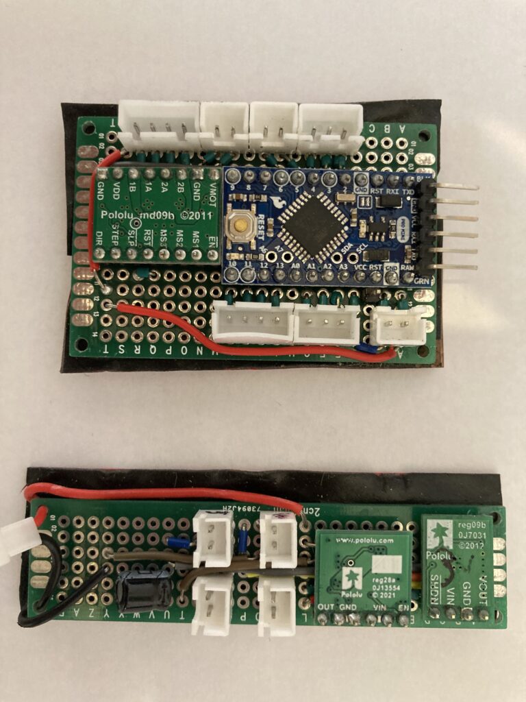
- Stepper Driver
- 12V step-up regulator
- 3.3 up/down regulator
- arduino pro mini
- decoupling capacitor
12V step-up is for the 5V motor (not a typo, reference the data sheet), 3.3V step-up/down regulator for the brains. Pololu made this nifty little device for battery powered applications. Lithium ion batteries are notorious for draining themselves to death AND their voltages drop as capacity drops. So, this regulator boosts to 3.3V regardless of battery voltage and has a cutoff at 2.7V or something to keep the battery healthy.
I split the boards into brains and power, thinking that I would make assembly sleeker. It didn’t and I want to redesign it. Next obvious step is a pcb with surface mount components to cut down on size. I’d like to bury the electronics underneath the actuator mount. I’ll add the schematic in the next couple of weeks (currently 3/14/2023) but, really, there isn’t much to it.
The Buttons
Ugh. I’m sorry about these, really. Archer Components has this awesome paddle remote that can mount anywhere on your bike and I have…this:
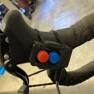
it’s so ugly. I’ve been very lazy about modeling a button-mount that matches the ergonomics of my brake hoods. It’s two push-buttons soldered to a small protoboard along with a common 3 wire 2.5mm jack inside of a 3d printed case. A male-to-male audio cable carries the signal back to the electronics board and tells our little pro mini what to do.
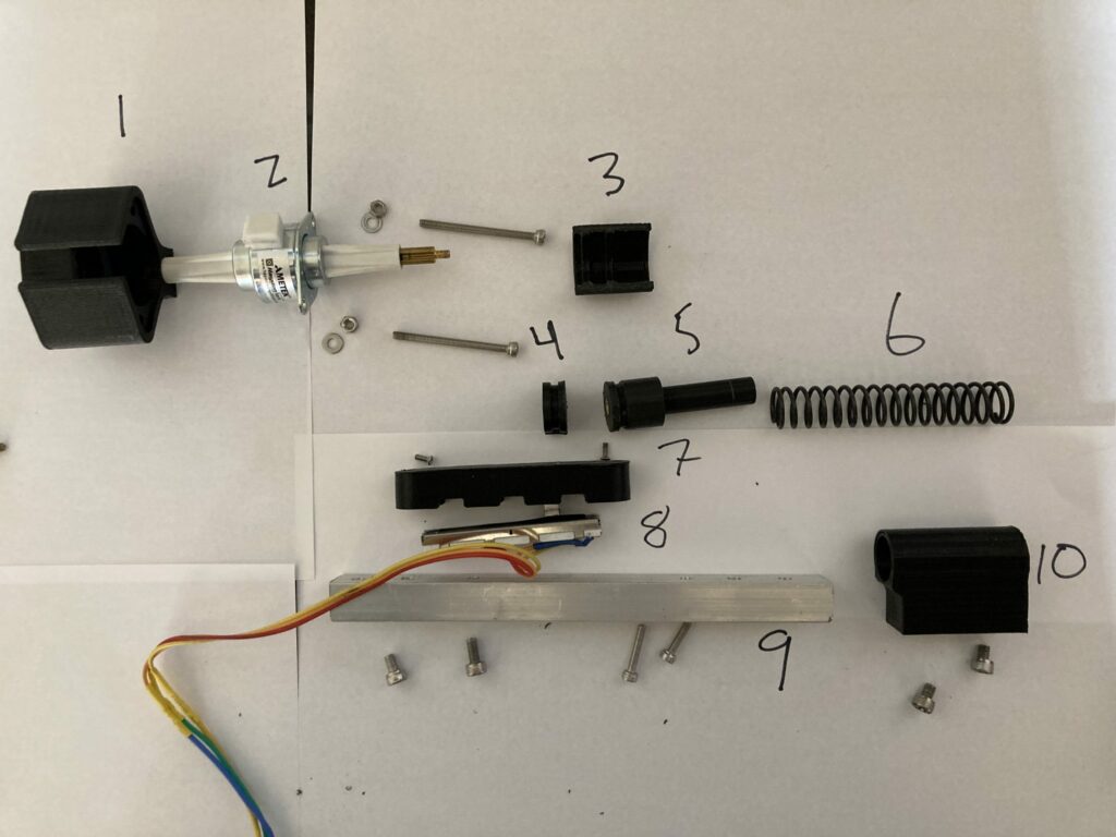
Mechanical Design
Finally the mechanical design. This is where I spend most of my time. I have a passion for good, responsive, and parametric 3d cad and this project was no exception. You’ll find the typical skeleton file with all the juice (dimensions, planes, naming conventions) and the parts and assemblies are just drop-ins. And just because I like doing them, exploded view and animation are below the break.
- Motor Mount
- Linear Actuator
- Adapters (sic) clip
- Potentiometer-to-actuator adapter
- Cable-to-actuator adapter
- Compression spring
- Potentiometer mount
- Slide Potentiometer
- Assembly mount
- Spring guide / cable guide
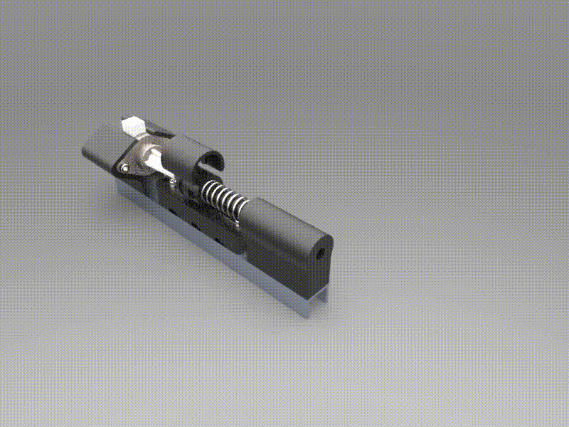
Fully assembled on the left. Less assembled on the right.
And that’s it. Pretty straightforward eh?! Not bad for a year’s worth of design…
The Files
Electronic Shifter CAD below. Available in solidworks and STL.
As always, Files are provided free (as-in-beer) and without warranty or expectation. If you end up downloading, printing, installing and using it would be nice if you dropped me a note to let me know.
Last note here, unlike the bar end shifters, I’m certain this is patent-able. Archer Components must have had a rock solid patent attorney because their patent covers everything under the sun for electronic shifting. But there’s always room for improved technology….unless you publish your ideas on the internet for all who seek them.
Final Thoughts
You know I’ve jumped to the top of Google for “3d printed bar end shifter” but my weekly downloads never top more than a handful. That was disappointing, I definitely thought more people would be interested in them. With this project, I had more realistic expectations…in fact I didn’t even bother to manage the SEO (because, eff SEO, seriously). I think very few people actually want an electronic shifter, those that do are willing to pay for one, and the hobbyists among us (dwindling I know) often don’t overlap with the cyclists.
But I love this thing. Seriously, I’m so happy with it. Shifts are precise and smooth and NOISELESS and it met all of my design objectives. Mission accomplished, and not like Dubya-mission-accomplished. Though, admittedly, design work is never done. My wife has even stopped laughing when I tell her I’m finished upgrading the bike.
Upgrades
So here’s a list of some stuff for the future build:
- Small indicator buzzer and/or LED
- low battery
- missed shift
- end of cassette
- power button
- I never unplug the battery, because three months of standby is a long time, but
- It would be nice and I could easily shut it down to conserve power using this https://www.pololu.com/product/2812
- A watchdog shutdown
- could also be implemented with that pololu button
- bluetooth
- running a wire from the shifter to my handlebars ALMOST defeats the purpose doesn’t it? So 2008
- This would also give me an opportunity to push instructions via an app, similar to Archer Components. It’d also be fun to do the app dev work
- A case
- Yeh, I sure didn’t mention this but guess what: The electronics are just totally exposed and I can’t ride my damn bike in the rain
- As a self described touring cyclist, this is a serious mechanical and moral failing
- I built a vacuum former to deal with this so an update is just around the corner. So. Many. Other. Projects.
Jesse DeWald
OwnerMr. DeWald is an engineer, educator, and problem-solver. He studied at The Cooper Union for the Advancement of Science and Art in New York City and has 15 years of industry experience in research and development, large-scale manufacturing, product design, and higher education. Mr. DeWald is currently the owner of DeWald Designs LLC.
Very impressive work!
However, I had some difficulties to understand the energy free spring balancers. When I look at the third equation I kinda have the feeling it is only correct in case the parallelogram is actually a rectangle. Otherwise one would have to apply the law of cosines instead of Pythagoras’ theorem and then I don’t see how to get rid of the cosine part.
Actually, in his thesis he treats a rhombus on pages 123f. And the math is still easy but a bit more complicated as he first has to divide the rhombus into four triangles. Although in the publication he speaks of parallelograms I think he actually has only a rhombus in mind.
Christopher, thanks so much for the comment and the kind words.
Check out the wikipedia proof of the “parallelogram identity” and let me know what you think https://en.wikipedia.org/wiki/Parallelogram_law#Proof
-JD
Great post! An epic journey, for your epic journeys. I hope that even though the shifter is noiseless it gives you a good “k’Chunk!” sound to let you now it’s done its job.
Hey John! Thanks for reading and checking in. And yes, there are still noises, but they are expected and indeed quite satisfying.
Thanks a lot for pointing me to the proof. I was obviously wrong.
I’m still struggling to find an intuitive account to these free energy spring balancers. But if it was too easy I wouldn’t be fascinated about it. 🙂
Thanks again for sharing this post.
Oh I think it’s not so much about being wrong as exploring. You’ll be happy to know that I also had a difficult time coming to terms with the behavior.
I ended up making one of the sliding ladders (with some bearings and aluminum bar I had laying around) to convince myself of the phsyics. That 12″x12″ contraption is still sitting on my desk.
Yo, temporary (or lazy permanent) waterproofing can be achieved with hot glue. When you’re done with it you can pick it off or melt it away with a heat gun. Hot glue is pretty handy stuff that way; discovered as much when I busted out a DIY Di2 loom: https://www.bikeforums.net/bicycle-mechanics/1230520-9150-controlling-9070-a.html
Oh yeah, a few years earlier I had a crack at DIY electronic shifting too, but my whole point was to implement half-step shifting (a whole other story: https://www.bikeforums.net/bicycle-mechanics/955466-half-step-triple-using-double-parts.html#post16877556 ), which was never going to fly without a specifically engineered FD cage. I coded Arduino to shift it, and was going to use countersprings like you, but just with servos and pulleys and kevlar string. Gave up on it though.
Good impressive work. Can this shifter be configured for 7spd to 12spd drivetrains ? Do you have plans for a front derailleur shifter for 2x and 3x ? And if yes do you think it’s possible add auto trimming based on the RD position like how Di2 works ?
Thanks for the note.
Assuming you pick your balancer-spring correctly, drive-train limitations are constrained only by 1) cassette width and 2) actuator stroke. My shimano 9 speed cassette is about 20 mm between smallest and largest cog and the linear actuator I chose has 30mm of travel. It could easily handle a 10 speed, maybe 11, probably not a 12 (though it’d be close).
I like where your headed! Yes I do have plans for my 3x FD almost solely for auto trimming. The design constraint is that I don’t want to add another actuator so I’ve been considering what a clutch mechanism would look like to engage one derailleur cable at a time.
It’s on the long horizon though, maybe by the end of 2023.
Hello, will you upload schematic?
small changes to the code, each gear has its number of steps and you can directly connect the motor with the shift cable mount. a threaded rod is enough for the motor axis and a nut for the cable fastening. I think it will be a perfect solution, I’m not into coding and it’s hard for me to make such simple changes. For now, I have completed a derailleur with a servo, however, it is not as ideal as this threaded motor
This is my coding dream 🥲 https://youtube.com/shorts/MEMDepeSEUA?feature=share
David, thanks for the comment. The solution in your video is very clever! I wonder if you can mount that motor without modifying the derailleur (or frame). If so then I may have to admit that it’s more elegant than what I have done.
I will upload the schematic in the next few weeks but it is very simple. -JD
just screw some fixing on the nut and the motor. It has to rotate, so you could probably print it and insert the bearing 😉 the screw with the thread “zeroes” the power consumption at rest, in the case of the servo I had to get rid of the spring because I burned 2 servos 😀 here the spring does not need to be removed 😉
I will try to do it without a schematic, but I have to buy a4988 because my tb6612 has different pins
Wow ! Thanks for sharing your work ! Your sketch is so well commented, as is the design. I put it in my favorites bar for one day. I’d like to hide the thing inside the wide downtube of my road frame, after debugging of course, it would be invisible and waterproof. Just wondering if you still plan to work on a schematics and custom pcb, I’d be really interested in having all those brains on one board instead of 3. Good luck !
Hi Vaclav, thanks for the note and kind words. I think the downtube is a great place to stash this. I’ve had this project on the backburner for some time but I do plan on drawing up the schematic…soon. Will def send a reply when it’s up.
I definitely would love to make this. And regarding your comment about “weekly downloads never top more than a handful”, I guess that if you made this into a a product or a kit you would see more interest. It’s the design and test that takes time, so people – and there are a few DIY’ers that actually pulls out the bike once in a while and wonders why electronic shifts should be as expensive as a new bike – knows that it will probably be easier to buy from you that to test themselfes…
In any case: You don’t mention where to buy the spring or the linear actuator. These two are pretty essential, so that is at least my excuse for not downloading your files and now sitting and do it myself (instead of just buying your kit, which I would defintely have done).
Hello PMB, thanks for the note! That comment (re weekly downloads) was in reference to my barend shifters. I never expected these electronic shifter files to be popular and, indeed, that’s proven prescient.
I’m not really in the business of making kits. Actually, I’m very much not in the business of making kits! I would struggle to compete with the off-the-shelf solutions on price and (most importantly) reliability.
That said, I do discuss both the spring and the actuator in the write-up. The actuator is from Hayden Kerk and is linked. The spring is trickier: it needs to be matched to your derailleur spring. You can do this by measuring the major and minor diameters of the spring and assuming it’s made of carbon steel. With that info, McMaster-Carr and Lee Spring are good starting places here in the USA. Happy to help if you get stuck so please reach out.
Where do you find the actuator screw separate from the motor? I’ve seen some nice actuators with motor on eBay. Maybe I can make something with this:
{ebay link redacted}Although that would be a different design from yours. On one hand it would be a little neater, however I’d need to design a housing for the linear potentiometer .
Hello Junkyard Biker! Thanks for checking in and for leaving a comment.
those HK linear actuators are a combination of stepper motor, acme lead screw, and acme nut. I’m sure you could make your own with off-the-shelf parts if you were so inclined, but my guess is it would quickly approach the cost of the hayden kirk… especially a used / refurbished one.
In any event, I removed the ebay link you provided because it’s unlikely to be helpful in the future. But I am also interested in those “micro linear actuators” particularly at a $8.99 price point! I *think* they use a dc gearmotor with limit switches…and without positional feedback, I’m not sure how easy it would be to dial in your gear changes.
The stepper motor lets me get pretty close to my target position and I can make small adjustments based on the reading from the slide-pot. The DC motor would either need some tuning or you’d need to build a simple PI control loop? I dunno, could be fun though 😉