
3d Printed Bar End Shifters
for the DIY cyclists out there
~~~~~ changelog ~~~~~
– redesign of friction-mode now uses an insert and self-locking cap screw
– reduced hardware
– bar-end tube assembly updated for reliable locating and rotation locking
– added a BOM (9/1/2024)
– corner reinforcement for barend base
– mating features on barend tube insert
~~~~~ changelog ~~~~~
The Need
If you’re just looking for the files you can find them here
As I mentioned in my introduction post, I’ve been pretty into cycling lately and REALLY into long distance cycling (touring, bikepacking, randonneuring, etc). I also love the look, feel, and balance of a good road bike. Oftentimes, these worlds are at odds with one another… which may be the primary reason I’m still tweaking my bike a year after I “finished” it. Combining the nuances of a road bike with the utility and comfort of a touring bike has proven to be a worthy design goal.
For instance: “brifters” (integrated brakes and shifters standard on most road bikes) can be obnoxious to integrate on a touring bike. If you love drop-bar handlebars and can’t use brifters you’ll need a solution that allows you to stop (important!) and to change gears. Bar end shifters to the rescue. Biketouringnews did a great write-up on “why” if you’re keen to know more.
3d printed bar end shifters to the rescue
So, yeh, why 3d printed bar end shifters? Cycling, cycling components, and the cycling culture in general are very expensive and, during Covid, got even more expensive. Because what better way to socially distance than to hit the open road!
Suddenly everything on eBay was labeled ‘vintage’ and three times the cost. And that’s 3x on many pre-existing x’s. Additionally, most local bike shops are overly concerned with the high-end cycling community. That leaves the hobbyists (me) left to fend for themselves.
Or, fend for themselves with the help of internet bloggers.
Design Requirements
First things first: Like most of the stuff I do, I’m not the only person to take a stab at this project. If you’re interested in some of the other solutions you can check out hackaday or do some Googling: they exist but there are limited options for comparison. And, arrogance aside, I think I’ve done it best.
Best, however, is relative and specific to my own design requirements. So those are important and I’ve listed them below, in no particular order:
Design Intent
In general, all of my CAD work follows these two basics of design intent:
- Customizable variables are stored in an easy to edit text file; and
- A skeleton sketch contains all important dimensions, reference geometry, and naming conventions;
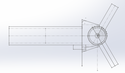
The inset graphic is a screen grab of the skeleton part used to drive all parts and assemblies. Everything you need is in this file.
The path of cable travel (and per ‘click’ lengths) are built in a block and those lengths are set by an external text file that holds a list of editable variables.
Admittedly, this may seem complicated if you’ve never designed a customizable part before. But by using this approach an end-user can easily modify these parts to suit their 10 speed derailleur. Actually any derailleur that is 10 speeds and under…just by changing the values in that text file. Pretty neat if you ask me.
The Solution
Indexing
I should note that building a friction-only lever is relatively easy and I’m sure some readers are befuddled about my labored pursuit of indexed shifting. In short, some cyclists prefer indexed gears and I’m one of them. So (to me) the effort was justified, but this was definitely the hardest and most interesting aspect of the design.
Sadly, the permutations of designs, concepts and decisions are fascinating (to me) but not very concise. The 1000-foot view is that I wanted to eliminate springs from the design and it had to be easy-to-assemble using only easy-to-find parts. I went through three concepts. The first relied on the compliance of the plastic as a “built-in” spring. That didn’t work. While PLA *is* compliant (it’s basically a fluid) it also has a low yield strength.
For the second, I tried to use an assembly of ball bearings and an array of detent features. This worked but it was a real nuisance to assemble. The ball bearings had to be very small (2mm) and had to be installed in-situ. In practice, they often fell out. This design also relied on the compliance of PLA, but the mechanism was more comparable to a cantilevered beam and thus more effective. Good compliance / bad assembly –> bad design.
Ratchet and Grommet
The final design has a ratcheting profile (‘hills’ and ‘valleys’) along the exterior of the lever. These ratchets engage with two 2mm stainless steel tubes that are not 180 degrees offset. At 120 degrees (the offset I chose), the reaction force component that is perpendicular to the axis of the handlebars is zero and the parallel component is….not zero.
I want that non-zero reaction force to cause a small, but not negligible, displacement. And I want that displacement to NOT occur in the PLA (ie little to no deformation). My solution was to add some low durometer rubber grommets in the central axis of the lever. These grommets compress when the ‘hills’ engage with the SS tubing, allowing the ‘valleys’ to detent without deforming the PLA.
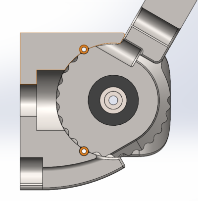
Section views below:
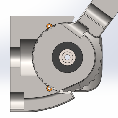
These section views illustrate the ratcheting mechanism. In compression (first image) the stainless tubes (in orange) interfere with the lever ‘hills’ and compress the rubber grommets (in black).
In equilibrium (second image) the tubes detent into the valleys and the derailleur rests in the appropriate gear.
Robust
I can hear the internet collectively complaining already. Why use plastic for components designed to see wear and tear? Particularly PLA?! And they’re not wrong. PLA is not known for its “robustness”. However, designed correctly, PLA is cheap, lightweight, and mechanically… acceptable. *If* designed correctly.
I went through a lot of iterations getting the detent dimensions correct. But once I did, the plastic behaved admirably and is still holding up after 500 1500 miles of hard-use. The wear-components of the mechanism are the rubber grommets and the stainless tubing and I’m really not concerned about either of those. In all, the design is pretty darn robust.
3D Printed!
Maybe this block belongs with the previous notes about being robust. They’re related. The only thing I will add here is that I hate post processing and will avoid it at all costs: all of the parts are designed so they can print without supports. This did require some compromises that may come back to haunt me if/when I choose to cast them.
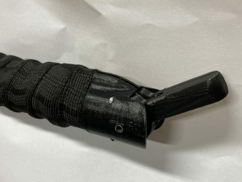
Hot Swapping
This was actually fairy easy to design. The only complications arose when I had to think about how to fabricate it. These pieces will *not* be machinable. But they could be molded with some slight modification.
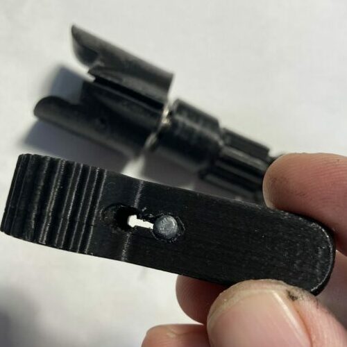
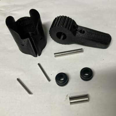
The important features to note here are
- the figure-eight cut-out in the lever (in my hand); and
- the slot along the main-body (on the table);
Most modern shifters require that the cable is pulled through the housing in order to remove the shifter from the bike. Both of the above listed features allow the cable to be inserted and removed ad-infinitum without the need to pull the cable through the housing.
Assembly
The Ratcheting section is a decent depiction of assembling the parts so I added the gif again. But we still want to know how to get it on the bike!
- Insert into the 3D printed bar end shifter housing into…the bar ends!
- You’ll need a 1/4-20 or 6mm button-head screw;
- You can buy bar-end inserts on amazon or at any bike shop. Or
- You can print the one included in the files and use the matching hardware;
- Slide shifter housing onto the cable housing;
- Tighten bar end sub-assembly until snug;
- Push cable end-stop through bar end lever, making sure to align correctly (see animation);
- Insert lever into shifter housing;
- Install 4mm stainless tubing, then the 2mm tubes;
- Set cable tension, barrel adjuster, and hit the road!
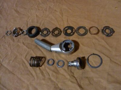
Production
I think there’s some merit to this design. Compare the disassembled image of a Shimano 9 speed bar end shifter from biketouringnews.com to the simple components in this design. Not only are there fewer consumables, but the ones I’ve used are dirt-simple. Total weight is 25 grams.
If moved to production, the cost of the (designed) parts could drop to less than a buck after you paid off your tooling. The consumables (in bulk) would be a few cents. Assuming you could sell 1M of these. I bet offering them at $10 a pop would be enough to turn some heads.
But you’re not going to sell 1M of these. The market simply isn’t big enough.
Final Thoughts
I’ve been pretty happy with the end results. The indexing is snappy and gratifying, the parts feel rugged, and carrying a set of spares costs me less weight than a pack of gum. Still, as mentioned, PLA is not ideal. Eventually they will break down due to UV, water, or wear. From a biodegradable standpoint this is mostly a win. But when you consider the cost to make and ship the PLA, it’s a wash for mother nature.
With that in mind, my next steps are to update the models for casting. I’ll start with a simple silicone tool and epoxy cast and work my way up to a desktop injection mold. If these were made of Nylon or Thermoplastic Polyurethane I think wear wouldn’t be an issue at all.
For all the patent attorneys out there, I think this design is novel, useful, and non-obvious. I also think it’s worth sharing. Releasing the design precludes me from having any intellectual property, but it also precludes others from doing the same and locking the knowledge away. I have a future post planned to explain my reasoning but suffice it to say that 75% of the work I do is on systems that were provided for free. LibreOffice, WordPress, Linux, Python, the list goes on and on.
The Files
Without further ado or transcription I present the files for making some of your own 3D printed bar end shifters. Hooray!
Files are provided free (as-in-beer) and without warranty or expectation. If you end up downloading, printing, installing and using it would be nice if you dropped me a note to let me know. BOM is below:
| Description | Vendor~PN | QTY | Link |
|---|---|---|---|
| PLA or PETG plastic | Various | Not much | Hatchbox |
| O-ring, dashcode: 110 | McMaster-Carr~9452K25 | 2 ea | McMaster |
| 1/4″-20 x 2.5″L SS Pan Head Screw | McMaster-Carr~91735A384 | 1 ea | McMaster |
| 2mm OD x 1mm ID x 20mmL SS tube | McMaster-Carr~50415K52 | 2ea | McMaster |
| M4x0.7Px25mmL SS Thread-Locking Socket Head Screw | McMaster-Carr~93705A827 | 1ea | McMaster |
| M4x0.7Px4.7mmL Brass Tapered Heat-Set Inserts for Plastic | McMaster-Carr~94180A351 | 1ea | McMaster |
I should mention that I’ve only released the models for a shimano 10 speed (or less) derailleur with standard 2.5 mm cable-pull. The de-facto internet standard for cog-spacing is an article on the artcyclery blog. You’ll find this article linked to in just about every cycling forum. In practice, I found three of my Shimano derailleurs had a range of 2.3 mm to 2.7 mm cable pull and, maybe not surprisingly, all of them averaged exactly 2.5mm. That’s the reason I used the external file for cable-pull variables: if we’re going to make something custom, let’s make it truly custom.
With that said, if there are any riders that want a specific cable pull (like Campagnolo!) send me note on my contact page and I’ll add it to the file server. Include the cable-pull per click if you know it.
Post Script
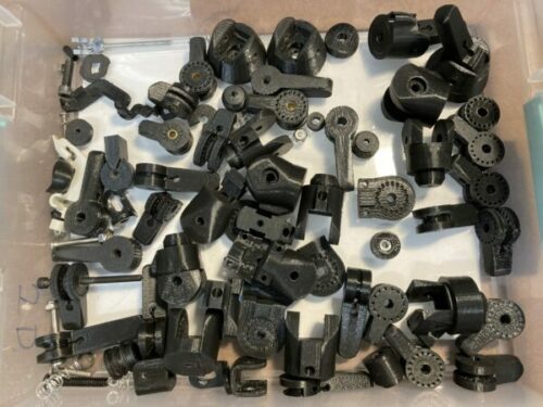
I made a LOT of prototypes for this design. The detents were a real nightmare and getting the dimensions and fits sorted required full prints. But, look, doing the math to model the deformations of a non-isotropic, pseudo-plastic would ultimately have defeated the purpose of rapid-prototyping. It’s always a balance.
Of course, I also spent a lot more money making these than I would have spent buying an off the shelf set. But I had a lot of fun and it gave me a good excuse to go on many, long bike rides through the mostly-mild winter.
I hope you enjoy using them as mush as I enjoyed making them.
Jesse DeWald
OwnerMr. DeWald is an engineer, educator, and problem-solver. He studied at The Cooper Union for the Advancement of Science and Art in New York City and has 15 years of industry experience in research and development, large-scale manufacturing, product design, and higher education. Mr. DeWald is currently the owner of DeWald Designs LLC.
I love this! Big fan of Bar End Shifters. You are right about the price hikes. Unfortunately I know nothing about 3D printing, LOL. Might be time to learnt. Though living in Cambodia I am sure I can find someone who is doing desktop 3D as side hussle/cottage industry. Thank you for you generosity.